 If we pursue this robot design the next level of development would also happen in Scratch. We’d boil down all these optimal parameters to a simple forward/back/left/right interface tied to arrow keys and drive around for a while! Only then would we finally transfer into textual coding, either into firmware via MOSS Flash or a dedicated mobile control app to distribute the behavior when a kit ships.
If you think programming with Scratch is only for kids and non-programmers, please open your mind for a minute. Here at Modbot HQ our MOSS Scratch plugin is the goto tool for prototyping new robot behaviors–even though we’ve got a bunch of hardcore programmers.
Why?
Simply because it leverages 100% of the capabilities of MOSS behavior in a package that facilitates real time iteration and experimentation – just like physical MOSS itself.
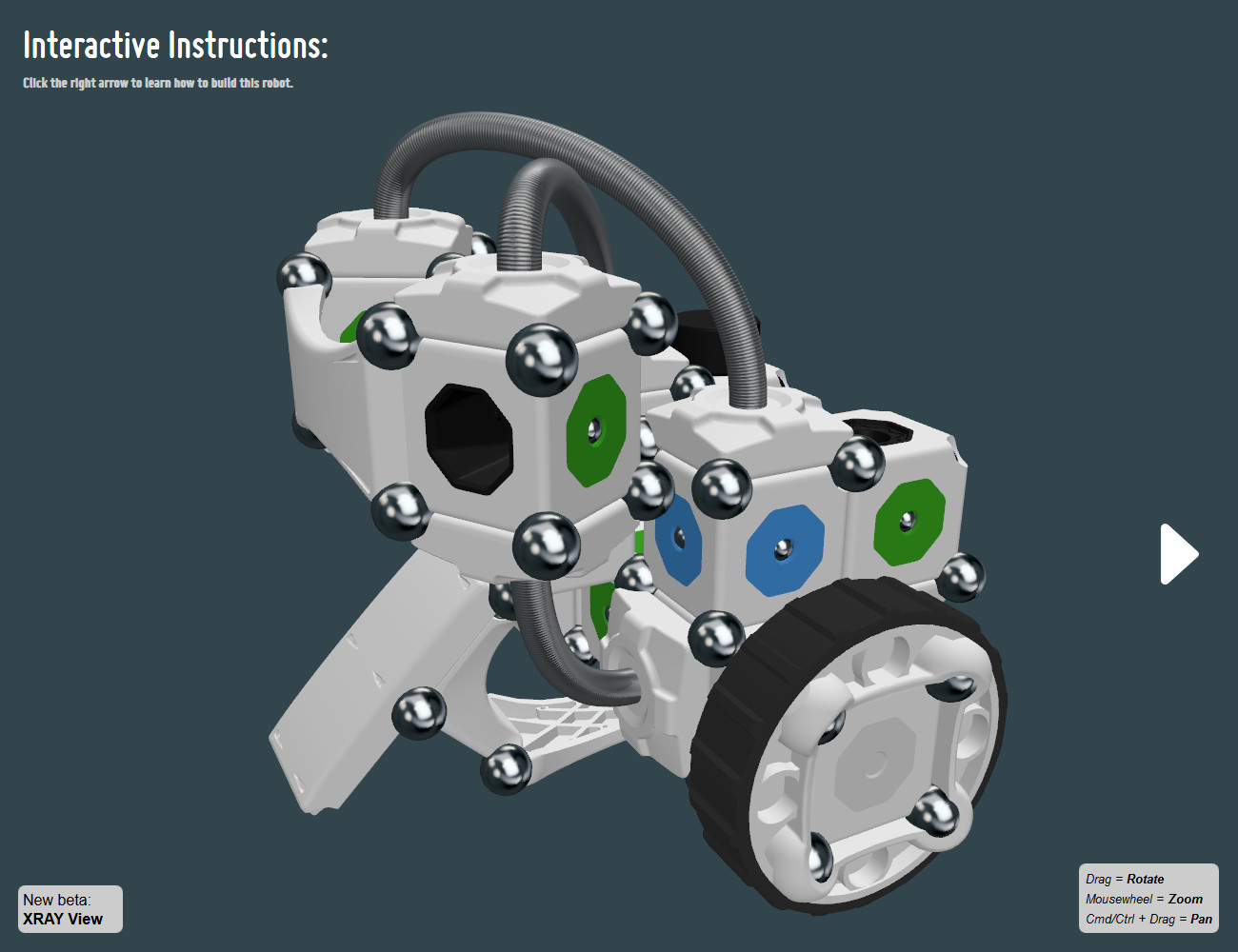
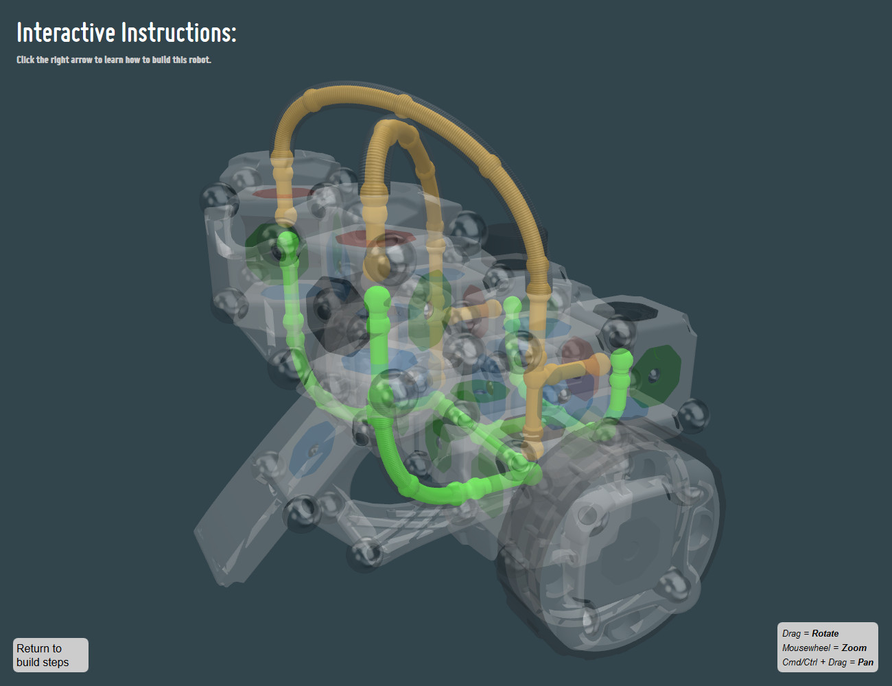
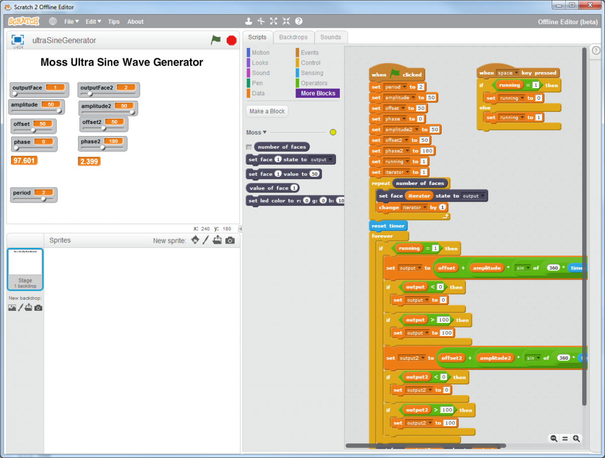
For example, we’re working on designing creatures for our next specialty artist kit of MOSS. This crazy snake-like one needed a synchronized motion pattern for the two pivot blocks in order to move at all. Starting with the sine wave generator example project included with MOSS Scratch we added a second channel and phase lag parameters in a few minutes. Immediately we had a robot writhing on the table and could quickly tweak the amplitudes, offsets, phase lags, and physical MOSS configuration to achieve optimal locomotion and turning.
 If we pursue this robot design the next level of development would also happen in Scratch. We’d boil down all these optimal parameters to a simple forward/back/left/right interface tied to arrow keys and drive around for a while! Only then would we finally transfer into textual coding, either into firmware via MOSS Flash or a dedicated mobile control app to distribute the behavior when a kit ships.
 If we pursue this robot design the next level of development would also happen in Scratch. We’d boil down all these optimal parameters to a simple forward/back/left/right interface tied to arrow keys and drive around for a while! Only then would we finally transfer into textual coding, either into firmware via MOSS Flash or a dedicated mobile control app to distribute the behavior when a kit ships.
